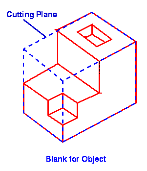
1) The geometry of the
object is given specified in the layer
format. ( see giving
input )
2) The blank size is
determined as ( Xmax Ymax Zmax
) block . The xy plane
of the blank is taken as
cutting plane .

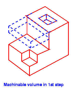
3) Lower cutting plane gradually
from Zmax position to get differance with
layers . The difference polygon(s) along with
the thickness of the layer forms machinable
volume .
4) The volume is tested
for concave point using
triangle test . Concave point is that point
on the surface which has visibility
range less than 180 deg .
5) Decide cutter change
using concave point .
6) With the data of
concave point and part edge the cutter
path is generated (equivalent to CL file) . The
g-m
code is generated from the
cutter path .
7) Repeat from step 3
untill no of times equal to the
no of layers .
