Homework 3
Manifold motion planning
You have a robot arm that you can move and see but you do not know its
dimensions or its kinematics (e.g. think of a baby that can look at its own
arm). The objective of this homework is to learn the "sensorimotor map" -
i.e. a map between its sensory space (the images that you can see) and its
control space (related to the joint angles).
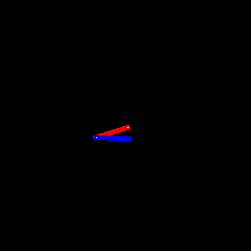
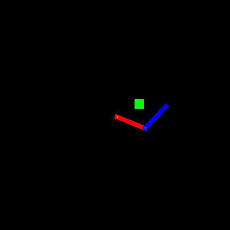
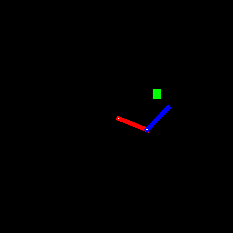
Here are some of the 3000 images that you have for the robot arm, along with
some 4-D control parameters (sin(Θ1), cos(Θ1), sin(Θ2), cos(Θ2)). You don't know this, but these "control
parameters" (q) have been generated by
taking the sines and cosines of the theta1 and theta2 angles for each pose.
Also, you have access to a motor that can move the arm to that pose.
B) Construct the lower-dimensional 2-D embedding for these arm images - this is the map for a large agglomeration of neighbourhood graphs. Make sure that you know original images that each node came from. Superimpose some of these images on the map to show how they vary.
C) Test how theta1 is varying along your map. Zoom into a part of the map, and show how theta2 is varying in that part. Comment on whether the map is able to capture the topology of the robot motion space.
D) Plot the embedding in 3D space, and zoom in and see what the topology looks like.
E) Using the 2-D map, let <v1,v2> be the 2D parameters for the robot in a certain pose. Let <q1,q2,q3,q4> be the corresponding control parameters(in file sinesCosines.txt in the dataset). Use any pattern-recognition algorithm (e.g. (multi-layer perceptron), to learn a map from <v1,v2> to <q1,q2,q3,q4>. Now try to learn the map directly from the Image to <q1,q2,q3,q4>. Which approach converges faster and why? Using 00001.png and 00161.png from this dataset as start and goal images respectively, plan the shortest path between them. Show your path on the map from (b), and mark the path with some of the images of interim points on the path.
F) Now consider the obstacle, as shown in imageObs1.jpg below. Here the obstacle is shown with the robot in the pose of image 0001.jpg. You will need to separate out the obstacle by subtracting the robot images from this obstacle image. Now, identify all the images where the some part of the robot hits the obstacle. Delete all corresponding nodes in the graph, as well as all edges incident on them from your graph and plot it. Now plan a path between the previous START and GOAL images on this attenuated graph. Show this path as in (c)
G) Now consider the obstacle imageObs2.jpg, and perform the path planning as
in (d) above. Explain the difference from (d).

|
|

|
| (0.3691,0.9294,-0.9277,0.3733) | (0.3056,−0.9522,−0.3348,−0.9423) | (0.1790,0.9838,0.4856,0.8742) |
What you need to submit:
A) Explore various dimensionalities for the manifold of these images. Draw the scree plot and justify that the dimensionality of this manifold is best explained at 2.B) Construct the lower-dimensional 2-D embedding for these arm images - this is the map for a large agglomeration of neighbourhood graphs. Make sure that you know original images that each node came from. Superimpose some of these images on the map to show how they vary.
C) Test how theta1 is varying along your map. Zoom into a part of the map, and show how theta2 is varying in that part. Comment on whether the map is able to capture the topology of the robot motion space.
D) Plot the embedding in 3D space, and zoom in and see what the topology looks like.
E) Using the 2-D map, let <v1,v2> be the 2D parameters for the robot in a certain pose. Let <q1,q2,q3,q4> be the corresponding control parameters(in file sinesCosines.txt in the dataset). Use any pattern-recognition algorithm (e.g. (multi-layer perceptron), to learn a map from <v1,v2> to <q1,q2,q3,q4>. Now try to learn the map directly from the Image to <q1,q2,q3,q4>. Which approach converges faster and why? Using 00001.png and 00161.png from this dataset as start and goal images respectively, plan the shortest path between them. Show your path on the map from (b), and mark the path with some of the images of interim points on the path.
F) Now consider the obstacle, as shown in imageObs1.jpg below. Here the obstacle is shown with the robot in the pose of image 0001.jpg. You will need to separate out the obstacle by subtracting the robot images from this obstacle image. Now, identify all the images where the some part of the robot hits the obstacle. Delete all corresponding nodes in the graph, as well as all edges incident on them from your graph and plot it. Now plan a path between the previous START and GOAL images on this attenuated graph. Show this path as in (c)
|
|