PROJECT PROPOSAL ON
BOOLEAN OPERATIONS ON POLYGONS
BY
S. PARTHASARATHY
.,
(M.Tech,Solid Mechanics & Design),
Roll Number : 9910524,
I I T-Kanpur.
CONTENTS
Constructive Solid Geometry (CSG) cannotes a family of schemes for representing rigid Rigid Solids as Boolean constructions or combinations of solid components via the Regularised Set Operations.
This CSG is unambiguous in representation. This can be considered as the building block of a Solid model. Even though there is a lot of ways for modeling a geometry this representation of a model through CSG is very easy for humans. This is because humans feel easy with basic Boolean Operations as they are ones to be performed to get the final model of a solid however the complication may be.
This project extensively explores the fundemental concepts of Data Structures and their effective utilisation and management. Presently this project is being done on 2D-polygons and can be extended to 3D-level also.
This project is in combination of calculating the properties of the polygons and development of quadtrees which are to be combined to get the software of manipulation of all the operations and calculations that are possible with 2D-polygons.
Need for CSG
Using CSG operations is easy for humans.
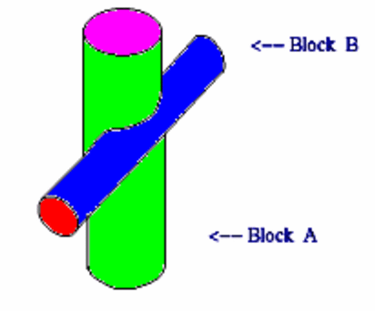
Consider the assembly
of cylinders. This is got by performing
Regularised Union operation
of Cylinder block A and Cylinder
block B , as shown below.
Here there is
no necessary of defining curves seperately
at the
meeting junctions
of the two cylinders.
With the Boolean
Operations intersection , negation operations
can also performed.
The whole assembly is
very well defined and modeled with
the
help of CSG Boolean
Operations.

SCOPE OF THIS PROJECT
This project is being done to make Regularised boolean operations on Non-Self-Intersecting Polygons. Also it is assumed that the boundary of the polygons are algebrically and semantically well defined.
The operations are done on the polygons by giving the command with Post-Script operators as
A
U B or
A I B or A - B
or B - A
U
---> Regularised Union
Operator
I
---> Regularised Intersection
Operator
-
---> Regularised Negation
operator
A,B are polygons up on
which those operations are to be
performed
METHODOLOGY
Click Here to view
Some Basic Concepts of CSG :
Constructive Solid Geometry (CSG) are ordered binary trees. CSG schemes are unambiguous but non-unique. The domain of a CSG scheme depends on the half-spaces which underlie its set of primitive solids and on available motional and combinational operators.
CSG trees with uninstantiated parameters can be used to represent
generic objects (also
called procedure-,macro-, or parametric objects or object schemata).The
validity of such generic object representations
also may be ensured easily.
CSG object is built from the standard primitives ,using regularised Boolean operations and rigid motions.The basic primitives for 2D operations may be any type of quadrilaterals and ofcourse any type of curvely bounded planes also provided the boundary should be well defined.
The basic primitives for
3D operations may be parallelopipped
(block) ,triangular prism,sphere,cylinder,cone,torus.They
are generic in the sense that they represent
shapes that must be instantiated by
the user to chosen dimensions.
After instantiation primitive objects
can be combined using regularised Boolean
operations.The operations are regularised Union
denoted here by RUNION , regularised intersection
denoted by RINT, regularised negation denoted by
RNEG.They differ from the corresponding
set-theoretic operations in that the
result is the closure of operation
on the interior of two polygons or
solids ,and they are used to eliminate
"dangling" lower dimensional structures.
LOGIC BEHIND THIS WORK
The Very
basic idea to find out the output
lies in the algorithm
of Point Membership Classification (PMC)
which is considered to
be the building block of this project.
Basically there are
3 operations that can be performed
on polygons.
They are Union,Intersection
and Negation.
This also requires to use the concept of Data structures effectively.
At the mixed stage of
polygon (The setup of the polygons from which
the required operations
are to performed) this PMC is used to
find out
the Line Membership
Classification (LMC) of each and
every edge
of the polygons.
Now each and every edge of one polygon is checked for its edges
being classified as outside or inside or on the other polygon and
are given respective flags to classify.According to the flags the lines of the polygon are cut in to seperate
entities and again stored as before.
RESULTS OF THE PROGRAM
Format of the input file
The input file which contains the data of the polygons is typed as follows.
Data entered are shown inside the braces
Enter 4 if there are no voids (3) <<-- means following data is hole.
Enter coordinates of 2 points ( 2 3 10 6)
Enter 1 if the hole is not closed (1)
Again enter 2 points (10 6 2 8)
Enter 1 if not closed (1)
Again enter 2 points (2 8 2 3) <<-- means hole is closed
Enter 1 if not closed (2)
Enter 1 if you want to enter
further holes' data (2) <<-- means no further holes
The following is for the outline
Enter the points of the line of
first edge (1 1 11 6)
Enter 1 if outline is not closed (1)
Enter second edge (11 6 1 12)
Enter 1 if outline is not closed (1)
Enter the next edge (1 12 1 1) <<-- means polygon is closed
Enter 1 if it is not closed (2)This same procedure is followed for the second polygon also.
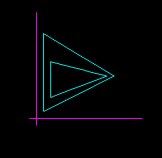
The following picture is the polygon represented

Logic implemented in this projectAs described in the "Logic behind this project"
the heart of this logic is Point Membership Classification and hence Line Membership classification .
Each edge is broken first according to where they
get intersected with the edges of the other polygons.Each linked list node
of the one supporting the polygon is given flags such as void or line,voidonline,linestatus etc.,
For each edge the LMC is done as to find whether
that line segment is "in(0) or on(1 for same sense & -1 for opposite sense)
or out(2)" of the other polygon.
Finally edge picking is done as to chose what edge for what operation.picking all 2s and 1s if that edge is not onon with an edge of a hole and picking all -1s for those edges which are onon with hole's edge is for UNION
In the above if we replace 2 by 0 we get the edges for INTERSECTION
Picking all those edges of linestatus 2/0 of one polygon and 0/2 for the other polygon and all 1s if that edge is onon with edge of hole and picking those with -1s if they are not onon with edge of hole gives firstpolygon-secondpolygon/secondpolygon-firstpolygon in the order specified above.
Sample input and output got
To Operate on A union B A int B A - B B-A
Achievement of Target---->> The code is written in C language which uses a linked lists of linked lists. So this supports any type of polygons with any type of configurations.
---->> Every edge of the polygon and its all statusses are not lost so that it is very easy to stictch.
---->> Can be converted in to more flexible and user friendly as this has the flexibility to handle any type of complexity.
---->> The main target reached was the ability to support any concave polygons which may result in holes and patches of polygons while during the operation and after that to store them to carry out further operations.
Some facilities yet to be added---->> Presently the points are to be added from the left bottom corner of the polygon and every thing in anticlockwise direction.
---->> Control doesn't know whether the polygon is closed or open.It assumes it as closed.
---->> It now supports all the polygons with 1 hole which now is a must to start the operation as right now it has some problem with traversing of pointers in the linked lists.
Link to C code
C CodeInput file to Second operation
Thanks
I thank Dr.Amitabha Mukherjee Instructor to this course whose guidance fully helped me in development of Logic and the Code.
Also I would like to thank my classmates especially G.Saravanakumar & K.N.S.Sudheer and my friend Swaroop who guided me in writing the program and who clarified my doubts whenever I got it.
Bibiliopgraphy
@InCollection(Aristides.A.G.Requicha 1980,
author= {Aristides.A.G.Requicha},
year= {1980},
keywords= {CAD/CAM,computational geometry,computer graphics,
design and manufacturing automation,geometric -
-modeling,representation of solids},
institution= {College of Engg and Applied science,The University of
Rochester,New York-14627},
title= { Representations of Rigid Solids:Theory,Methods &
Systems},
booktitle= {Computing Surveys},
month= { december},
volume= {12},
annote= {
Computer based systems for modeling the geometry of rigid solid
objects are becoming increasingly important in mechanical and civil
engineering ,architecture and other areas.The variety and uses of systems
embodying representations of solids are growing rapidly ,but so are the
difficuilties in assesing the current designs ,specifying the characteristics
that future systems should exhibit ,and designing systems to meet such
specifications.The first part introduces a simple mathematical frame
workfor characterising certain important aspects of representations.
The second part uses the frame work to describe and compare all of the major
known schemes for representing solids.The third part briefly surveys extant
geometric modeling systems and then applies the concepts developed in the
paper to the high level design of a multiple representation geometric modeling
system which exhibits a level of reliability and versatality superior to
that of systems currently used in industrial Computer-Aided-Design and
manufacturing.}
@incollection (Avraham Margalit and Gary D.Knott1989,
author= {Avraham Margalit,Gary.D.Knott},
year= {1989},
keywords= {Polygons,intersecting,manifold,domain,dangling edges},
institution= {Computer Vision Laboratory,Center for Automation reasearch,University of Maryland,
College Park,MD 20742 and Dept of Computer science University of Maryland.},
title= {An algorithm for Computing the Union intersection or differnce of two polygons},
booktitle= {Computer and Graphics},
month= {april},
volume= {13},
pages= {167-183},
annote= {The algorithm uses a boundary representation for the input and output polygons.Its domain includes simple polygons as well as polygons with dangling edges,vertices of degree greater than 2,and holes with in the area of the polygon.It is facilitated by the use of efficient data structures. - parthasarathy}