|
Tomographic Data |
AMIT (95023)
NILANJAN KARFA (95173)
Project Proposal: ME 751 Computer Aided Engineering Design
Indian Institute of Technology - Kanpur : August 1998
The project aims at providing a solution to the problem of getting a 3D model from data collected using Tomographic Techniques. Tomography, which already plays a vital role in medical diagnostics, is a means of obtaining the view of a section of the object under observation. In the field of medicine this technique helps doctors in determining the state of affairs inside the patients body.
This technique is also used for obtaining similar data about the structure of other physical objects, and allows us to look into material properties and defects of the object.


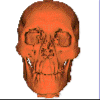
We propose to extend the application by providing an interface, which will transform data obtained from a tomography system into a solid model. This conversion will provide engineers with a means of applying various simulation techniques for testing and manipulating the properties of the object. A designer in the CAD domain will be able to test fragile and expensive specimen using this computerized model. Applications of this work also exist in the field of reverse engineering. Any part, or subsystem can be scanned using tomographic techniques and after the proposed conversion its model can be used to redesign the system. Analysis of reasons of failure of parts and their redesign can also be carried out using the model that our application will generate.
Many machines have components that were designed several decades ago, the technology existing at that time proved those components to be excellent but with several advances in technology in the time that passed, these components have lost the credibility that they once had. We often feel the need to redesign some of these old components, but drawings for the old designs are difficult to obtain or at least difficult to interface with the modern tools for design i.e CAD tools. To get over this difficulty the drafting of the older design has to be done from scratch. A more accurate, viable and comfortable option is giving the existing component to a scanner which would send the data corresponding to the old design to a computer which in turn will build a 3D model to be used for design modification.
Our program, on successful completion, will enable a user to just take the old component, place it on a Computer Assisted Tomography (CAT) table and allow the tomography system to generate the scanned output, this output will be automatically piped to our program which will convert the data into a 3D model of the component and then pass it on to a CAD package using which design modifications, testing etc.can be performed.
A lot of work has already been done on the problem we propose to solve. In fact, the problem, if seen in two parts, is already solved, what actually remains is the amalgamation of the two solutions to obtain a final solution. The two parts referred to are :
Large volumes of literature exist on the solution of both these problems. Tomography has been used for the past two and a half decades as a powerful tool in medical imaging systems. Many tools, which provide sectioned views of the anatomy on a living body, have been developed and successfully put to use. Similary, in the field of CAD and Graphics, many algorithms have been developed for generation of 3D models from 2D sections.
Takahashi, provides a concise overview of the techniques used in Computer Assisted Tomography, including algorithms used for image reconstruction and viewing. A more detailed description of Image Reconstruction as applied to Tomography has been given by Herman. These books are helpful in understanding the basic concepts of Computer Tomography and also for implementing algorithms for efficient reconstruction of images from Tomographic Data. A finite element maximum entropy approach to reconstruction of tomographic images from sparse data sets has been presented by Smith, Zoltani, et.al..
The problem of finding smooth surface approximation to a series of cross-sections has been solved by Park and Kim, in the domain of CAD. Their approach can be used to convert 2D contours to a smooth B-spline surface. We will need a bridge between the two approaches for image reconstruction and surface generation. The image reconstruction algorithms output images whereas the surface generation algorithm requires contours, the bridging program has to convert images from the first part to contours using standard edge detection techniques.
Tomographic Data constitutes a matrix of values corresponding to absorptions of the incident rays. The rays are cast from different angles so that the absorption coefficient of individual points can be uniquely determined. At each angle the rays are cast from different positions so as to scan the entire object.
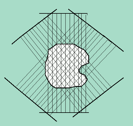
This data can be converted into images using the matrix inversion technique described by Herman. These images are then converted to contours by standard edge detection filters. The contours thus generated can now be passed further for generation of the 3D model.
The generation of 3D surface model from the images of contours involves three basic steps :-
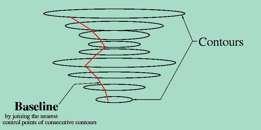
The curve fitting algorithm has been described by Park and Kim. Intermediate curves are then constructed on the knots generated during B-spline fitting. Finally the surface is "skinned", i.e. a bicubic closed B-spline surface is generated using the intermediate curves constructed on the common knot vectors. Thus we end up with a 3D model of the surface of the original object scanned.
We are presenting the surface in the form of a parametric equation that can be used by any CAD modeling tool to visualize and manipulate the object. The algorithm has been implemented only for one surface, but can be easily extended for an object having internal cavities and multiple surfaces. The only complexity involved in this extension is the identification of contours corresponding to the different surfaces, but this can be easily resolved if the order of occurance of the sections (contours) is known.
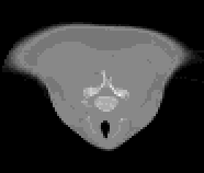
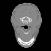
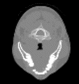
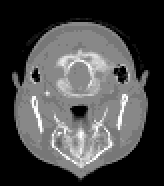
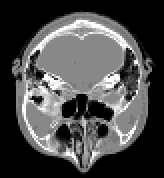
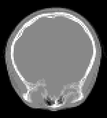
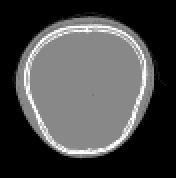
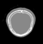
The input to the program will be tomographic data which, for each section, is a matrix of values corresponding absorption coefficients obtained at uniform spacing at different angular positions. This data is first converted to images of sections using various techniques like matrix inversion or maximum entropy. Images obtained for eight sections of an object are shown below.
The final output of the program is a 3D model of the object whose sections were initially taken. The models can then be viewed or modified using any standard CAD tool.
For our program we take the input in a form shown below:-
5 		# No of sections provided
ell1.pgm 10	# image file for each section and the Z location of the section
ell2.pgm 30
ell3.pgm 50
ell4.pgm 70
ell5.pgm 90
ell6.pgm 110
ell7.pgm 130
ell8.pgm 150
The program loads the images from these files and the performs the edge detection procedure on them. The Polygon approximated from the images is returned in the form of a linked list of vertices. Some assumptions about the images and the resulting edges are made,
We tested our program on some pseudo data. The images used had simple polygonal sections shaded in the same colour. Images form one such set are shown below:
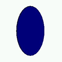
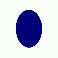
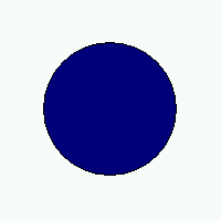
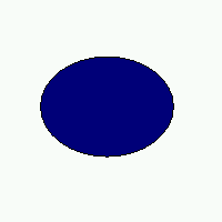
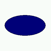
Screenshots of the window displaying salient vertices for the approximated polygin are also shown:
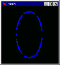
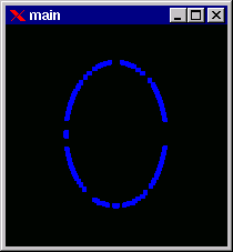
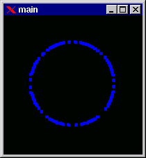
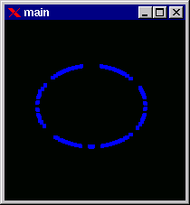
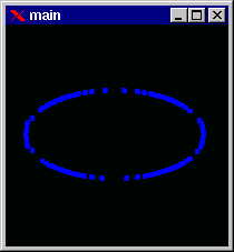
After the polygons are determined they are aligned to obtain the approximate order of occurance of the vertices in each polygon. This alignment is of great importance because it controls the slopes and shape of the surface to be finally generated.
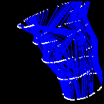
The final output of our program is a file named [infile].bcbs. This file contains the parameters required for constructing the surface in the following format :
[no. of knot points]
[knot 1]
[knot 2]
[knot 3]
.
.
.
[no. of control points per section] [no. of sections]
[x11] [y11] [z11]                 # coordiantes of the first control point on
				  # the first contour
[x12] [y12] [z12]		  # coordinates of the second control point on
				  # the first contour
.
.
.
[x21] [y21] [z21]		  # coordiantes of the first control point on
				  # the second contour
.
.
.
A program processing this output can find the blending function using these knot points and control points given by our program, which in turn will define the B-Spline equation of the 3D surface approximated by our program.
There are several difficulties in implementing this program on a small system like the one we are using. The process stack of the kernel seems to overflow and write onto the heap where the main memory is allocated. This occurs because of the highly recursive computations involved in finding out the blending functions appropriate for the given contour points. A large amount of memory is also required for the allocation of the several matrices required for the same computations.
Another difficulty is in finding an approximate polygon for the bounding contour of the image given. The chain-code approach has been employed to find the salient vertices, this algorithm causes problems whenever the edge detected is not closed. Also the chain code generated for most contours (even polygons) contains a large number of points, which leads to a very large size of the set of approximating control points, which in turn is responsible for the large memory requirement.
For the source code of this project CLICK HERE