****************Project Report**********************
Aircraft for standing in air requires an upward force to sustain its weight and experience a drag force for moving in viscous medium(Air). This upward force (LIFT) is generated due to peculiar shape of wing. For designing the aircraft ,therefore, we need to select/choose a shape of wing which can give us the required lift(=weight you want to sustain). This clearly shows that we should have a means to tell us the lift generated for any given shape. Our present program intends to do in same direction.
Some research in the field of aerodynamics are based on the generation of new airfoil surfaces and studying the flow over it to find an optimum design. The whole design of the airfoil mechanically is a tough job and further is the testing in the wind tunnels and if there is slight modification in the shape the whole process has to be repeated. Our programme gives a solution to this with in the vicinity of inviscid flows. Although it can't predict the flow over the airfoil completely. But it gives a fair idea about what the flow is going to be.
The basic thing required in flow calculations through FEM is mesh generation. To generate a mesh we need to provide a boundary for the airfoil over which the testing is required. It is helpful to provide boundary in terms of points on the upper and lower surfaces for a desired NACA specification. One can use this code prior to FEM generation code to provide input for the mesh as airfoil boundary.
But none of them deals with recently founded shapes & their programs are still in fortrain.
1.Introduction
The lift force generated by a given shape of wing, is dertermined by integrating the lift force generated by the cross section of the wing (AIRFOIL) .In nearly all commercial aircrafts the airfoil sections used are ones developed by NASA(called NACA airfoils; NACA- old name of NASA)
2.Basic temanology of airfoil
3.Description of NACA designated airfoils
NACA 4 - series :(say NACA 2412 )
2 - max. camber in % chord
4 - position of nax camber in tenths of chord
12 - max. thikness ratio(w. r .t chord)
Similarly NACA 5- series & NACA 6 -series represent various airfoil properties
4.Procedure
Coordinate Generation :
NASA has developed diferent equations for camber and thickness for its different airfoils series.
Example: (NACA 23015)- 5 series airfoil
a. Mean camber line
Y/c = k1/6[cub(x/c) - 3x1 sqr(x1/c) + sqr(x1)(3-x1)(x/c)] ; for 0<= x/c <= x1.
= k1 cub x1(1-x1/c)/6 ; for x1<= x/c<=1.
b. Thickness Distribuion :
Yt = +/-5t[.2989sqrtx-.126x-. 3616sqrx+.2543cbx- .1015 fourx]
Upper and lower surface cooradinates can be generated by
Xu = X - Yt sing ; Xl = X + Yt sing;
Yu = Y + Yt cosg; Yl = Y - Yt cosg;
where tang = dy/dx ;
In case of four series modified,five series modified,one series and six series airfoils the equations are not very trivial. The generation of surfaces for these series requires solving different matrix equations which give various constants related to the specific airfoil.These constants can be used in equations to find coordinates of points on the upper as well as lower surface.
Velocity Distribution Calculation :
velocity distribution over airfoil at given angle of attack & reynolds no. is calculated using thin airfoil theory . After getting the coordinates on the upper and the lower surface of the airfoil the effective camber and effective thickness is found as required by above mentioned theory.After doing necessary corrections for the sweep as well as for the angle of attack the velocity at each and every point on the surface is calculated, which is essential for pressure coefficient calculation.
Pressure distribution Calculation :
Bernoulli's theorem says that
p + 1/2 .den.sqr(v) = p(at infinity) + 1/2 .den . sqr (v at infinity)
where den = density;
v = 3 - dimensional velocity;
Using velocity distribution and above theorem pressure distribution (p) can be calculated.
Lift and Drag :
Once pressure distribution is known calculation of lift and drag is one hand job. We just integrate it in horijontal and vertical direction and take there components for given value of angle of attack.
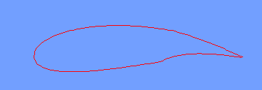
When NACA airfoil (any series) number is given as input in required format (mentioned in README) program opens a window having blue color as background and draws a nicely shaped airfoil in red color. Thereafter presure distribution on upper and lower surface of airfoil is shown in green color ( We get different distributions -graphs for different angle of attack ).
Here are some results which are obtained using this code :

This is a four series airfoil NACA6612.
This is a five series airfoil NACA23012

This is a 6series airfoil NACA66212

This is NACA 5 series modified airfoil 4300632
All these are generated by this programme
Here are some results of pressure coefficient calculation;
The figure below shows the pressure distribution for a NACA0012 airfoil at 0.0 degree angle of attack.
The same thing for NACA2412 - a cambered airfoil and NACA66212 at 1 degree angle of attack is shown below.
There are some limitations for using this code .