Here we give the directions to the user who would be using our program.
We have used two primitives :
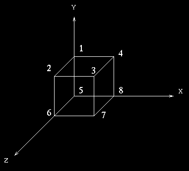
- Unit Cube with its eight vertices being (0,1,0), (0,1,1), (1,1,1), (1,1,0),
(0,0,0), (0,0,1), (1,0,1) and (1,0,0) in the order as given in the figure below. Any rectangular space can be obtained by applying scaling, rotation and
translation transformation to this unit cube.

- Sphere. Its radius and center has to be specified
Input
Two input files are to be created :
- File containing the objects
- File containing the CSG-hierarchy
Format for file containing objects
no_of_slabs
             /*  slab 0 */
   color
   scale_x         scale_y         scale_z
   rot_x           rot_y           rot_z
   trans_x         trans_y         trans_z

             /*  slab 1 */
                   .
                   .
                   .
             /*  slab n */

no_of_spheres
             /* sphere 0 */
    color
    radius
    center_x        center_y       center_z

             /* sphere 1 */
                   .
                   .
                   .
             /*  sphere n */

view_window_length  view_window_height      view_window_z
view_rotate_x       view_rotate_y           view_rotate_z
view_trans_x        view_trans_y            view_trans_z
A sample file in above format
1
   7
   4.0 2.0 4.0
   0.0 0.0 0.0
   0.0 0.0 0.0

2
   5
   2.0
   4.0 4.0 0.0

   7
   3.0
   3.0 4.0 0.0


4.0 4.0 200.0
0.0 00.0 0.0
0.0 0.0 10.0
Format for specifying object's CSG-hierarchy and data-file containing objects
Object-Filename infix-expression
A sample file
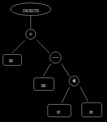
datafile1 (s0+(b0-(s1*b1)))
Following figure is the graphical representation corresponding
to the object specified by the infix-expression in the sample file given above.

Note1 : s0 means sphere 0, b0 means slab 0, and so on..
Note2 : + means Union, * means Intersection and - means
Difference.


